Tightening Torque
This paper, authored by Ron Dise, describes the methodology used to establish a tightening torque for any application using PEM® brand fasteners
Customers frequently ask about tightening torque for mating threaded hardware used with our self-clinching fasteners. Many PEM® brand fasteners are specialty items that may have limited axial strength. Tightening torques (unified/metric) are published for studs and most nut products. Published values are based on an assumption of the k value or nut factor being 0.20 which may not be correct in all situations. This paper describes the methodology used to establish a tightening torque for any application using PEM brand hardware. The following variables affect the tightening torque and therefore must be known in order to estimate a tightening torque.
- The PEM® brand part number
- The strength level, material, and finish of the mating nut or screw
- Any special feature on the mating nut or screw such as a large diameter flange or conical washer
- Material and finish of the attached part which the mating nut or screw will bear against
With the above information the axial strength of the assembly can be established. Establishing the axial strength involves determining the lowest of the following four loads
- External thread tensile strength
- External thread stripping strength
- Internal thread stripping strength
- Strength of the PEM® brand fastener body
- Flush head stud strength is limited by the head strength
- Strength of some nut product, such as type F, is also limited by head strength
The next step is to select the target preload. Typically, the target preload is based on 75 % of the minimum yield strength of the assembly. Torque is only an approximate measure of preload and as discussed below, is heavily influenced by minor variations in friction. By targeting only 75% of min yield, low friction variations are less likely to cause yielding during tightening. The danger in targeting an even lower percentage is that a high friction variation will result in low preload. In many joints some minimum level of preload is required for the joint to remain reliable in service. Another reason to set the preload at 75 % of min yield is that during tightening the external thread sees both tensile and torsional loading. However, this is only applicable when the external thread tensile is the limiting factor.
The next step is to estimate the torque-tension relationship. This is the most challenging step because it is often difficult to know the exact values of the friction coefficients involved. Tightening torque can be divided into the following three components.
- Load inducing torque which is a function of lead angle and is not affected by friction
- Thread friction torque which varies with µt, the thread friction coefficient
- Torque to overcome friction at the loaded face of the turned member which varies with µlf, the friction coefficient for that interface
The load inducing torque is typically only 10 to 20 % of the total tightening torque. This means that 80 to 90 % of the torque is used to overcome friction. This is why even minor variations in friction coefficient can have a major affect on the torque-tension relationship. There are three possible methods to estimate the torque-tension relationship. Each method is discussed below in increasing order of rigor. As a general rule, the more critical the joint, the more rigorous the method of establishing the torque-tension relationship should be.
Using a k value or nut factor –Although it is the least vigorous, this method is frequently used because it is very simple. The equation below is used to establish the tightening torque based on the target preload.
T = L x k x d
where: T is the tightening torque in in-lb. or N∙m
L is the target preload in lb. or kN
k is a dimensionless factor known as the nut factor or the torque coefficient
d is the nominal major diameter in inch or mm
Obviously, the challenge with this method is to choose the correct value for k. Values can range from 0.10 to 0.30. For un-lubricated zinc plated hardware, a value of 0.20 is a good place to start.
Using the long equation with actual geometry and estimated coefficients of friction – This method uses the equation below which considers each of the three tightening torque components.
- T = L x [ P/(2 x π) + (PR x µt/ cos 30˚) + (Rtm x µlf)]
- T is the total tightening torque, in-lb. or N·m
- L is the clamp load, lb. or kN
- P is the thread pitch, inch or mm (really lead, but same as P for single start)
- PR is the pitch radius or PD/2, inch or mm
- µt is the coefficient of friction between the mating threads, dimensionless
- Rtm is the effective radius of the loaded face of the turned member, inch or mm
- µlf is the coefficient of friction between the loaded face of the turned member and the mating surface, dimensionless
The challenge with this method is choosing values for µt and µlf. If one or more of the threaded components is coated with a lubricated topcoat with a specified coefficient of friction the task is easier. However, it is important to keep in mind that there are two different friction interfaces and three material and finish combinations involved as shown below.
- Thread friction interface
- One material and finish is the PEM® Brand hardware
- The other material and finish is the mating nut or screw
- Loaded bearing surface friction interface
- One material and finish is the mating nut or screw
- The other material and finish is the attached part
The PEM® brand hardware is only one of the three materials and finishes involved, so adding a lubricated topcoat is helpful, but still allows friction variation. The mating nut are screw is one of the surfaces in both interfaces, so adding a lubricated topcoat to it is very effective at reducing friction variation.
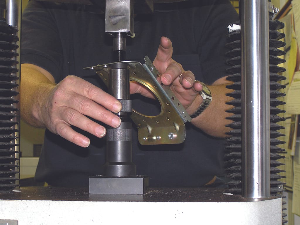
Conducting torque-tension testing of a simulated joint – This the most rigorous way to establish the torque-tension relationship. It is expensive and time consuming and therefore may only be warranted for critical joints. When this method is used, it is important to make sure the actual hardware is used. In addition to using the actual PEM® brand fastener and mating threaded hardware, a test coupon of exactly the same material and finish of the attached part should also be used under the turned member.
PennEngineering® has torque-tension testing capability at several global locations and can assist with torque-tension testing when warranted. The customer will need to provide the actual mating threaded hardware and coupons of the attached part material and finish.
The final step is to establish the tightening torque. For the first two methods above, the respective equation will give the torque after the k value or friction coefficients have been chosen. If torque-tension is used, statistical analysis of the data can be used to establish the tightening torque.
Establishing tightening torque is a complex process and this blog can not address all situations. PennEngineering® has experienced technical professionals available to assist customers with establishing mating hardware tightening torques for not only PEM® brand fasteners, but also ATLAS® and SI® brand fasteners.
For questions, please email us at [email protected]