Fastening Hardware Using Surface Mount Technology
Surface mount technology can now be used to add fasteners to printed circuit boards where various types of fasteners are adhered directly onto a solder pad on the surface of…
Abstract
When assembling printed circuit boards, electronics manufacturers face a difficult choice. They can deal with the inconvenience and poor productivity of loose fastening hardware. Or they can use broaching fasteners, which hold circuit boards securely but can too easily damage fully populated boards if not installed properly.
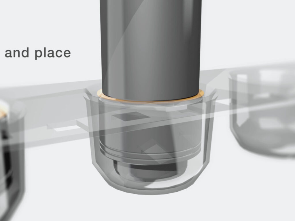
Surface mount technology can now be used to add fasteners to printed circuit boards. This uses a system in which various types of fasteners are adhered directly onto a solder pad on the surface of the PCB, using the same soldering processes as the board’s other electronic components. This system is designed with productivity in mind. The fasteners come in tape-and-reel packages that are suitable for use with existing pick-and-place machines. A fastener can now be installed as quickly as 1/3 second as opposed to up to 30 seconds for a secondary operation.
Not only are there labor savings, but scrap savings as well versus the alternative method of broaching. Manufacturers typically install broaching fasteners once the boards have been fully populated with electronic components. But the broaching process, which may subject the boards to significant amounts of stress after they are populated, can ruin these very expensive populated PC boards.
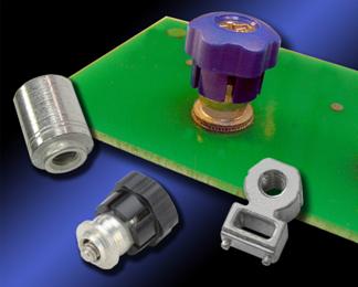
There are fasteners currently available in several varieties as standard products including panel fasteners, spacers, nuts, and right-angle styles. The panel fastener is appropriate for applications that require easy removal and reinstallation of circuit boards. The spacers are the choice for board to board stacking and nuts are a convenient means of fastening, where previously a broaching or loose fastener was selected. Right angle fasteners take a unique approach to joining components with a 90° separation.
Background
There are many ways to fasten hardware to PC Boards. The most common of these are loose spacers. These are often in the form of plastic or metal columns used to offset two boards. These spacers must be placed secondarily, sometimes snapping onto the PC board, sometimes screwing together with another component. This secondary process is often if not always manually performed representing a large investment in time to accomplish.
Loose nuts and screws are handled much the same. Used during assembly the handling can be an issue because of the fine work necessary to align all parts typically on both sides of the PC board. Care must be taken so that any dropped hardware is identified and removed so as to not cause rattle, or worse, shorts and product failures.
To get away from loose components and simplify the assembly process, many companies utilize broaching spacers or nuts. This hardware permanently fastens to the PC board so that the handling becomes much simpler by eliminating one of the loose components. The broaching however is achieved by pressing a knurled component into a slightly smaller hole in the board, forcing the knurls to cut into the board. If done improperly it can cause problems to the integrity of the board. To reduce potential failures, sufficient keep-away areas should be provided around the fastener to keep small traces clear of the “broached” area and close-to-board edge distances must be maintained. Problems and board damage can also occur if during the installation process the parts are misaligned while being pressed into the mounting hole.
Other methods of attachment exist but are not as readily used. Adhesives, buttons, keyholes and interlocks, and others are all used, and all have both advantages and disadvantages. One common factor all these options share is that they all must be placed on the board or assembled. This represents a cost, typically in manual labor which can be very high. And any additional touches to the board represent additional opportunities for quality problems to arise.
The Solution
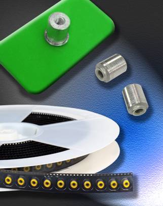
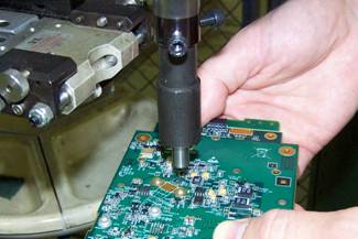
The solution to these issues is to eliminate the need to manually place the hardware after the board is populated. Instead, the better solution is to place the hardware while the board is being processed using the equipment and infrastructure that already exists in the PC board market. By placing the hardware on a tape and reel and presenting it just like other electronic components, it can be installed with conventional surface mounting equipment. This utilizes the machines and processes that already exist and eliminates the need to have further human contact with the part.
Cost Comparison
By taking the human element out of the equation, serious cost savings can be achieved. Any secondary operations that can be eliminated represent cost savings, but those associated with fasteners are often more expensive processes. For example, installing four broaching fasteners into a board can represent 80 seconds (20 seconds each). If labor is assumed to be 30 USD per hour, which represents almost 0.78 USD in the time to install the part. Added to the cost for the four broaching fasteners, the assumed cost is 0.05 USD each, and the total cost to place these fasteners on the board is 0.98 USD per board.
The other factor to consider is that where there are additional operations and human interaction, there is an added chance for quality failures. If the fastener-associated failure rate is 0.1% and the populated board is assumed to be 100 USD, the quality cost per board is 0.10 USD. These failures may come from multiple sources, but as noted above, common causes of failure are as follows:
- Micro-crack proliferation severing traces in any of the multiple layers of the board.
- Misalignment of the fastener during installation loading causes large-scale cracking or breaking of the board.
- Misalignment of the fastener during installation led to later assembly issues.
- Incorrect hardware is being installed.
All these add to the fastener cost associated with the board. Totaling the cost associated with fastener installation with the cost for quality failures yields 1.08 USD total cost for the addition of four fasteners to a board. The numbers above represent conservative averages in the industry, but it can be seen how the numbers could be scaled to a particular application.
If the solution on the right can be applied to this comparison considerable cost savings can be seen.
The quality issues associated with cracking and misalignment can be eliminated because the fasteners are installed automatically with the pick and place robotic equipment placing all electronic componentry. The process is non-intrusive to the board and can therefore not expose the board to cracking. Additionally, as the parts are packaged on a tape and reel and not loose and dumped into bowls, the chance of mixing the parts with other hardware is very slight (only if an operator chose the wrong reel of hardware). This, therefore, eliminates the quality costs associated with the fastener.
The cost to install the fastener is also eliminated. The only manual cost would be to place the reel in line with the other reels on the pick and place machine. The machine will automatically take the part from the tape and place it on the board. This nearly eliminates the cost of installation.
To be competitive on the cost of installation, the fastener packaged on a tape and reel for this application example must be less than the total cost of 1.08 USD for four, or 0.27 USD each. Each application will have different costs associated, but similar calculations can be performed to determine the break-even point for costing1.
Performance Evaluation
The cost is only a portion of the feasibility evaluation; the part’s function must also be considered. For this style of part, the function is represented by the part’s ability to adhere to a pc board. This is a function of the part geometry and surface finish, the solder paste used and the conditions of the surface mounting.
Loose nuts, spacers, and standoffs are typically steel, plated with tin to aid in soldering. Parts placed in solder on the land of the pc board adhere to the land once the solder is reflowed. Solder is not typically thought of as a mechanical attachment means, but rather a way to pass a current while holding something in place. This changes that paradigm instead of making the solder’s primary function akin to glue. Because of this, the adherence of the fastener to the board is largely based on the characteristics of the solder. Different solder pastes yield different performance results. Mechanical performance for a soldered joint with a threaded fastener should be measured in two ways: forced to remove and torque resistance.
As a baseline PennEngineering has tested two different solders with 30 pieces. The specifics of the leaded and lead-free tests can be referenced in Tables 1 and 2.
Table 1: Leaded performance testing parameters
| Oven | Quad ZCR convection oven with 4 zones |
| High Temp | 496ºF / 258ºC |
| Board Finish | 62% Sn, 38% Pb |
| Board | .062″ thick, Single layer FR-4 |
| Screen Printer | Ragin Manual Printer |
| Vias | None |
| Paste | Amtech NC559v2 63/37 (leaded) |
| Stencil | .0067″ / 0.17mm thick |
| Land Thickness | .0015″ |
Table 2: Lead-Free performance testing parameters
| Oven | Quad ZCR convection oven with 4 zones |
| High Temp | 518ºF / 270ºC |
| Board Finish | 62% Sn, 38% Pb |
| Board | .062″ thick, Single layer FR-4 |
| Screen Printer | Ragin Manual Printer |
| Vias | None |
| Paste | Amtech NC559LF Sn96.5/3.0Ag/0.5Cu (SAC305) |
| Stencil | .0067″ / 0.17mm thick |
| Land Thickness | .0015″ |
The results of the experiments can be seen summarized in Tables 3 and 4. It can be seen in these two tables that the results of the experiment showed a considerable variation due to the conditions and solder used.
Table 3: Leaded solder performance results
| Pushout | Torque-out | |
| SMTSO-440-12ET | SMTSO-440-12ET | |
| Min | 63.0lb | 9.00 in-lb |
| Max | 101.0lb | 13.00 in-lb |
| Average | 82.8lb | 10.23 in-lb |
| Sigma | 9.2lb | 0.88 in-lb |
Table 4: Lead-Free solder performance results
| Pushout | Torque-out | |
| SMTSO-440-8ET | SMTSO-440-8ET | |
| Min | 37.0lb | 4.25 in-lb |
| Max | 87.0lb | 11.25 in-lb |
| Average | 56.5lb | 8.56 in-lb |
| Sigma | 12.4lb | 1.45 in-lb |
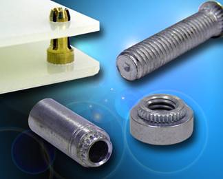
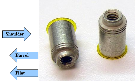
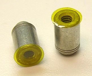
These tests were done with a part that had a locating pilot that sat in a hole on the PC board. The pilot sits in an un-plated through-hole and the shoulder of the barrel of the part rests against the land on the board. This shoulder of the barrel is what is soldered to the board, the solder fillet forming between the barrel and the land on the board.
Further testing has shown that while not required, a pilot helps aid in positioning and provides stability to the fastener. For nuts, the threads typically are entered from the board side, so earlier engagement can be achieved by threading a pilot that sits inside the thickness of the board. Also, in short spacers, additional thread engagement is achieved by using the thickness of the board.
Additional experiments showed consistent results, that leaded solder gave a better bond than the lead-free solder. However, different profiles, solders, quantities of solder, and board finishes all have an effect on the performance results. The bottom line with performance is that in critical applications, it is advisable to ask your surface mount fastener supplier for samples that can be tested in conditions mimicking those that will be seen in a production environment.
Other Concerns
Mechanical performance is only one aspect of the fastener that should be considered. Other concerns include tin whiskers, feeding issues and stencil design.
Tin Whiskers are a poorly understood phenomenon. The organization iNEMI offers some very good guidelines and assistance to understand this on their website. While many platings exist, pure tin is the most common for use in surface mount fasteners. In applications where tin whiskers are a concern, care should be taken to ensure that fasteners tin-plated are of a matte tin and have been bake annealed to relieve embitterment. Though this does not guarantee that whiskers will not develop, it is a leading recommendation against their growth.
Another concern is with the pick and place devices. Not all fasteners have a convenient, exposed flat surface that can serve as the suction point for the pneumatic pick and place finger. This is most often seen in threaded or through-hole spacers and nuts. In these cases, a patch should cover the top of the part so that suction can be achieved against the patch. The patch then must go through the oven. The patch typically must only be removed in the cases where the thread must enter from the patched side of the hole.
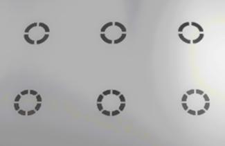
A surface-mounted fastener can be soldered directly to the surface of a PC board, but, more often a pilot is included on the fastener to aid in stability and placement. The pilot sitting in a hole requires that the stencil mask the hole while exposing the land to solder. This can be achieved in numerous manners, but the most common is the use of a spoke design as shown in figure 7.
These spoke designs prevent the solder paste from entering the un-plated through hole on the PC board, but ensure that paste is applied to the land. The fact that areas of the land do not receive solder does not adversely affect the performance as the solder evenly distributes during the reflow process.
Alternate Designs
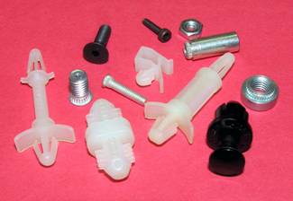
Spacers and nuts represent most of the fasteners used in the PC board industry, but there are many other types of fasteners that are used. Some of these can be surface mounted while others don’t lend themselves to the process. Figure 8 shows several designs readily available.
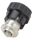
Figure 8 shows the spacer, but also shows an example of two other fasteners that lend convenience and reduced costs. The first of these is a panel fastener. Several variations exist, but the common feature is a threaded screw or pin that retracts and advances to engage a nut or internally threaded feature. Figure 9 shows a panel fastener in detail.
It can be seen in figure 9 that the fastener has several common features that have already been explained. The fastener has a pilot that rests in a hole on the PC board. It also has a shoulder that rests against the land of the board. This particular fastener has the screw thread and plastic cap initially separate so the retainer can be placed on the board and run through the oven. After the reflow, the cap and threads snap onto the retainer completing the fastener.
Another unique fastening solution offered for surface mounting is a right-angle fastener, also shown in figure 8, but detailed in figure 10 below. This fastener provides threads parallel to the PC board allowing a component to be mounted 90° to the board.
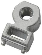
The shape of this fastener allows the part to be picked up from the pick and place machine without a patch as it is presented in the tape and reel with the two small pins downward and the flat portion of the head exposed to the pneumatic finger. The two pins at the bottom act as two very small pilots, providing both stability and locational accuracy during placement. The step along the bottom allows the solder fillet to be formed along this edge even while the face of the fastener is flush against an edge of the PC board. Lastly, the rectangular hole reduces the mass and allows the fastener to heat quicker and draws less heat away from surrounding components on the board.
Other designs including snapping fasteners and externally threaded fasteners are also feasible. A creative approach to fastening can often find a means to create the attachment, even in unusual applications.
Conclusions
Recent advances in fastening technologies have made available a new means to fasten to a PC board utilizing the infrastructure currently available. By surface mounting the fastener to the board, significant cost savings can be achieved without compromising the performance of the design. Fasteners fed on a tape and reel, assembled with pick and place equipment, and reflowed alongside other electronic components have the potential to save handling costs and reduce quality failures associated with manufacturing.